
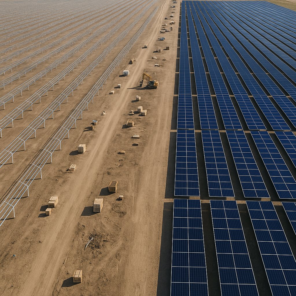
Retrofitting a cleaning robot onto a finished solar plant is always possible. It is just more expensive than it needed to be. Row lengths that do not match the machine, a 40 mm height step between adjacent tables, no water line within 600 metres of the far block: none of these are hard problems during design, and all of them become permanent constraints once the piles are in the ground. Designing a solar plant for robotic cleaning costs almost nothing at the drawing stage and determines your O&M cost for the next 25 years.
Why cleaning belongs in the design review
Most plants are designed around three optimisations: energy yield, capex per watt, and constructability. Cleaning enters the conversation later, usually when the first performance report shows soiling losses that the financial model treated as a fixed 2 percent.
By then the geometry is fixed. And geometry, more than any other factor, decides whether automated cleaning is straightforward or awkward on a given site. A plant designed with cleaning in mind is not a different plant. It is the same plant with a handful of dimensional decisions resolved in the right direction.
The EPC has no incentive to make those decisions unless the owner asks. So the owner has to ask, at the layout review, before the single-line diagram is frozen.
Table geometry: the decisions that matter most
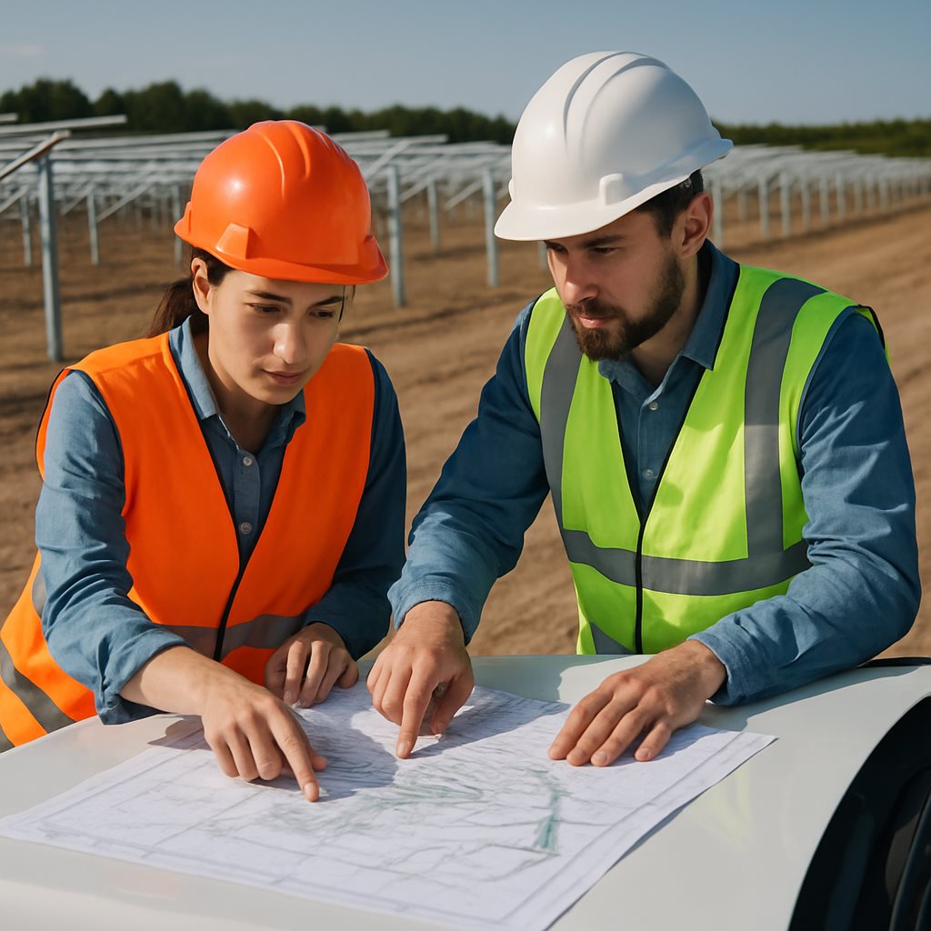
Automated cleaning works along continuous runs. Everything that interrupts a run costs time, and time is capacity.
Row length and continuity. Longer uninterrupted runs mean fewer transitions and higher throughput per machine. Where the layout must break for a road or a drainage channel, group the breaks so they align across rows rather than staggering them, which keeps machine transfer predictable.
Module orientation. Portrait and landscape both work, but they produce different travel distances and different numbers of inter-module gaps for the same array area. Decide it deliberately rather than inheriting it from the racking quote.
Gaps between modules. Racking suppliers set inter-module spacing for thermal expansion and clamp geometry. Small, consistent gaps are fine. Large or irregular gaps interrupt the cleaning path and leave unswept bands at the module edges, which is where soiling concentrates anyway.
Table-to-table alignment. This is the single most under-specified item on any drawing. If adjacent tables are not level with each other within a tight tolerance, a machine crossing between them either cannot make the transition or does so with an impact load. Specify a maximum height difference between adjacent tables in the construction tolerance schedule, and inspect it at handover rather than discovering it during commissioning of the cleaning system.
Terrain, slope and tracker layouts
Undulating terrain is the reason a lot of sites end up with misaligned tables. Following the ground contour saves earthworks and costs alignment. The right answer is site specific, but the trade should be made explicitly, with the cleaning implication priced rather than ignored.
Slope along the row is usually more tolerable than slope across it. Cross-slope introduces a twist between tables that shows up as exactly the height step described above.
Single-axis trackers add a variable that fixed-tilt plants do not have: the array position changes through the day, so cleaning has to be coordinated with tracker control. That coordination is routine when the two systems are specified together and awkward when the cleaning system arrives three years later, a point we cover in more depth in the article on cleaning solar panels on trackers. During design, the practical requirements are a defined stow or cleaning position, a control interface, and confirmation that the tracker can hold position for the duration of a cleaning pass.
Water, power and docking infrastructure
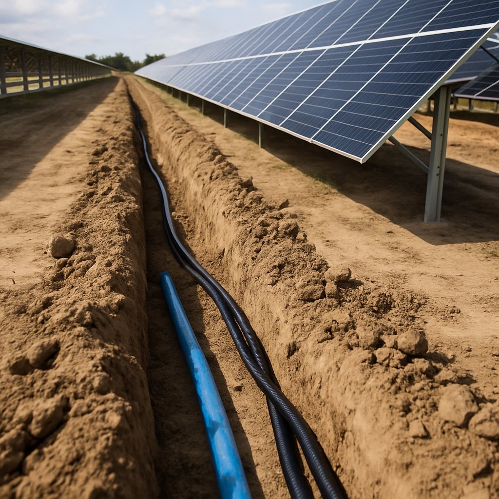
The infrastructure decisions are cheap during civil works and disproportionately expensive afterwards, because retrofitting means trenching through a live plant.
- Water distribution. Run a supply line to each block during the main trenching campaign, with tap points at a spacing that matches the cleaning system. Adding pipe alongside DC trenching costs a fraction of a separate later excavation.
- Water treatment and storage. Allocate a footprint next to the substation or O&M building for filtration, treatment and buffer storage, sized to the volume the cleaning method requires rather than the volume a manual crew would need.
- Power at the array. Charging and docking points need a small auxiliary supply distributed through the field. Auxiliary circuits are easy to include in the original cable schedule and painful to add later.
- Docking and parking positions. Machines need a defined, protected home position per block, ideally with shade, drainage and a hard standing area.
- Access tracks. Inter-row tracks should be wide and firm enough for the service vehicle that moves and maintains the equipment, not only for the pickup truck that inspects it.
- Connectivity. Cleaning systems report performance and faults. Field coverage, whether cellular or a site wireless network, should be verified across the whole array, including the far corners that nobody surveys.
Rooftop and constrained sites
Commercial rooftops have their own list. Structural load capacity governs everything, and the relevant question is not just the mass of the machine but where that mass sits when it is parked. Parapet height, safe access routes, service walkways and drainage paths all shape whether an automated system can be deployed, and they are architectural decisions made long before anyone thinks about maintenance.
Roof arrays also tend to be interrupted: skylights, HVAC units, vents and cable trays break the array into small islands. Designing the layout with a small number of larger continuous fields, rather than many fragments, makes the difference between a system that cleans efficiently and one that spends most of its day repositioning. The practical benefits at that scale are set out in our overview of rooftop solar panel cleaning robots.
Rail-based or rail-free, and when to decide
A rail-mounted system has to be planned with the structure, because the rail is part of the structure. A rail-free machine that travels the array under its own guidance imposes fewer permanent commitments and preserves the option to change approach later.
The design implication is a timing question. If the plant will be built now and the cleaning method chosen later, a layout with clean geometry and generous tolerances keeps both options open. If the cleaning system is being procured alongside the plant, the two designs should be developed together. The trade-offs between the two architectures are compared in the article on rail-free versus rail-based solar cleaning robots.
Retrofitting an existing plant: what to check first
For operating assets, a short survey answers most of the question before anyone quotes.
Measure the height difference between adjacent tables at a representative sample of rows, including the worst terrain on site. Record row lengths, module orientation and the pattern of breaks. Note tracker type and control system. Map the distance from existing water and auxiliary power to each block. Check inter-row access width and ground firmness in wet conditions. Confirm connectivity at the array edges.
Those six items determine whether a retrofit is a simple deployment or a civil works project. Sites that were built with reasonable alignment tolerances almost always fall into the first category, which is the whole argument for specifying that tolerance in the first place.
A design checklist for EPCs and owners
- Maximum height step between adjacent tables, stated in the construction tolerance schedule and inspected at handover
- Row lengths and break positions aligned across the array rather than staggered
- Consistent inter-module gap, coordinated with the racking supplier
- Defined tracker cleaning position and a control interface for it
- Water line and tap points to every block, installed during the main trenching campaign
- Treatment and storage footprint sized to the cleaning method
- Auxiliary power and docking positions distributed through the field
- Service-vehicle access on inter-row tracks
- Verified network coverage across the full array
Solaris Hydrobotics reviews layouts against this kind of checklist for ground-mounted solar projects at the design stage, and the recurring finding is the same: the expensive constraints are almost always dimensional, and almost always free to fix on paper.
The bottom line
Cleaning is the only routine O&M activity that touches every module on the site, several times a year, for the life of the asset. Designing the plant so that work can be automated is not a specialist requirement. It is the same category of decision as leaving room to replace an inverter.
Ask the geometry questions at layout review, put the alignment tolerance in the contract, and run the pipe and the auxiliary cable while the trench is already open. If a cleaning approach is under consideration for a project still in design, that is the cheapest moment in the asset’s life to get it right.
Frequently Asked Questions
Can cleaning robots be retrofitted to an existing solar farm?
In most cases yes. The determining factors are table alignment, row continuity, and the distance from existing water and auxiliary power to each block. A short site survey covering those items is usually enough to establish whether deployment is straightforward or requires civil work.
What table alignment tolerance does robotic cleaning need?
The requirement is system specific, but the principle is universal: adjacent tables should be level with each other within a tight, stated tolerance so that a machine can transfer between them without impact loading. The tolerance belongs in the construction specification and should be verified at handover.
Do cleaning robots work on single-axis trackers?
Yes, provided the tracker can hold a defined position for the duration of a cleaning pass and the two control systems can communicate. Specifying that interface during design is simple; adding it to an operating plant with a closed tracker controller is considerably harder.
How much does it cost to make a plant robot-ready?
The dimensional decisions, including row continuity, module gaps and alignment tolerance, cost nothing beyond attention at design review. The infrastructure items, mainly water distribution and auxiliary power, are marginal when installed alongside the main trenching campaign and expensive when trenched separately later.
Does terrain rule out automated cleaning?
Rarely on its own. Slope becomes a problem mainly when following the contour produces large height differences between adjacent tables. Where earthworks are being minimised for cost reasons, the cleaning consequence should be evaluated explicitly rather than assumed away.
Should the cleaning system be procured with the plant or afterwards?
Procuring together allows the two designs to be developed as one and is the lower-cost path overall. Where that is not possible, building the plant with clean geometry and generous alignment tolerances preserves the option without committing to a specific technology.